
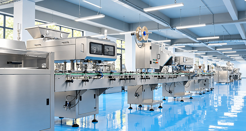
How Much Floor Space Does a Bottling Line Need? (And How to Lay It Out)
Plan for the machines, maintenance, traffic, and clear height. Check the layout against your actual room.

Floor space for a bottling line includes more than the machines themselves. Allow for maintenance and changeovers, people and material movement, loading height, buffering, and primary and secondary packaging areas. Adding machine lengths together will not tell you whether the line fits, and no single area multiplier applies to every configuration.
Send us your room’s length, width, and height, along with door and column locations. Our factory can prepare a free initial layout and space check. We first lay out the actual configuration, then assess whether the room supports operation, replenishment, and maintenance.
Service access Clear height and layout Free initial layout
1.Floor space isn't just the length of the line
To judge whether a line fits, consider how the space around it will be used. Operators need access for replenishment, open service doors, maintenance, and material movement. Check overhead clearance, buffering, and connections between packaging areas as well. Machine dimensions are the starting point for the layout.
Think of parking a car: fitting the body into a space does not mean the doors can open or people can get out. A bottling-line drawing can show non-overlapping machine outlines and still leave no room to stand, remove parts, or replenish materials.
| Space to check | What to show on the layout |
|---|---|
| Equipment footprint | Actual outlines of machines, conveyor connections, feeders, and accessories |
| Maintenance and changeover | Service sides, door and cover openings, parts removal, and working space |
| People and material routes | Room doors, operator positions, replenishment routes, and finished-product movement |
| Usable clear height | Clearance below beams and pipework, plus working space for taller equipment |
| Buffering and staging | Any specified bottle accumulation and temporary positions for bottles, caps, and finished product |
| Primary and secondary packaging areas | Where each process sits, the boundaries, and how conveyors connect the areas |
Coordinate these spaces on the same drawing rather than estimating each separately and adding them up. An aisle should not become permanent packaging storage, and an open service door should not block the only access route.
Before purchasing, define the equipment configuration, then overlay the room’s fixed features and actual working methods. The question is whether the line can operate properly in your building, with access for the tasks around it.
2.The space everyone forgets: maintenance access
Service-side space depends on how doors and covers open, which parts must come out, and how people and tools reach them. A narrow gap between a machine and the wall does not establish maintenance access. Check each machine’s actual structure and the work that must be done around it.
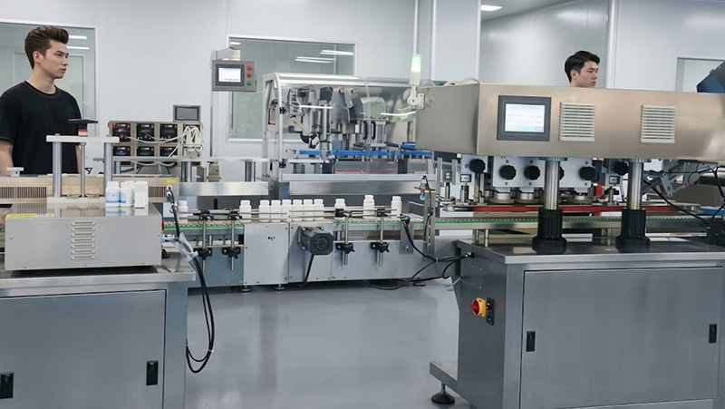
We have encountered this problem in actual projects: a machine was too close to the wall, and even with its service door open, there was no room for the technician to do the work. Once equipment is installed, making space for a repair becomes much harder.
Confirm that the maintenance can be carried out. Check door movement, technician positions, and parts-removal space before locating a machine beside a wall.
Show door openings and maintenance tasks together
Mark each machine’s service side, door and cover opening directions, and any components that need to be removed. Then check whether walls, columns, neighboring equipment, or conveyors occupy those spaces.
Two machines may both rely on the same empty area for opening doors or removing parts. Identify that overlap and assess it against the actual maintenance procedures. Looking only at stopped machines with their doors closed will miss it.
Changeovers and cleaning need access too
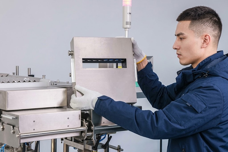
Replacing vibratory trays, adjusting guides, and removing contact parts for cleaning all require access for people and parts. Our another article “How Fast Can You Switch SKUs on a Bottling Line?” explains the changeover tasks; the layout needs to establish that those tasks can actually be carried out in the room.
Keep reserved service space available during daily production. Storing empty cartons or spare packaging there takes that space away again after installation. Confirm the required area against the selected equipment and site working requirements.
Reserve space to do the maintenance
Wall too close: opening and access are restricted
The machine footprint may fit while service-door movement and maintenance work remain obstructed.
Room to open the door and carry out the work
Check door openings, parts removal, technician positions, and tools together.
The practical check: After opening the service door, there must still be space to complete the maintenance. Confirm the area for the actual machine and site.
These sketches compare spatial relationships, not dimensions for one model. They imply no universal wall clearance or statutory aisle width.
3.Walkways and material flow

Mark doors, columns, and fixed equipment before drawing operator, replenishment, and finished-product routes. A neat row of machines can still make material handling awkward. For an L-shaped or U-shaped line, recheck access after each turn or return leg, including routes to stations on the inside of the layout.
Follow the process direction first: where do product, empty bottles, and caps enter, and where do completed bottles go? Then check how operators reach counting, cap feeding, labeling, and other positions that need attention.
| Walk the route | Questions to answer |
|---|---|
| From the room door to loading points | Can product and packaging reach the stations without an unnecessary trip around the line? |
| From operator positions to each station | Can people reach controls, replenishment points, cleaning areas, and changeover positions? |
| From line discharge to finished-product staging | Will product removal or temporary storage obstruct normal access? |
| Around corners and columns | Can the actual handling method pass, and can room doors open as required? |
| Into an L-shaped or U-shaped layout | Is there a clear route to inside stations, and does it conflict with replenishment? |
Plan packaging staging at the same time. Empty bottles, caps, labels, and cartons need defined positions before replenishment can be assessed properly. An aisle drawn as clear space may otherwise become the place where everything is stored during production.
For an existing facility, mark the equipment and routes that must remain. Also check the doorways and turns the new machines will pass through during installation. Equipment may fit its final position but still encounter an obstacle on the way into the room.
Overlay equipment, access, and routes
Navy arrows show bottle flow. The teal dashed route indicates movement through the room. Mark doors, columns, and fixed constraints first, then check access for people and materials.
The five boxes illustrate process and space relationships, not an actual configuration, machine count, or room size. Replan door access and staging for the site.
4.Look up: overhead height matters too
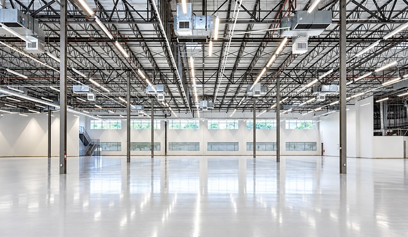
Check usable clear height at the position where each machine will stand. Product elevators, cap elevators, and sleeve labelers may rise above neighboring stations, while beams, pipes, or other overhead services reduce local clearance. The room’s overall height is only part of the check; the location of taller equipment matters too.
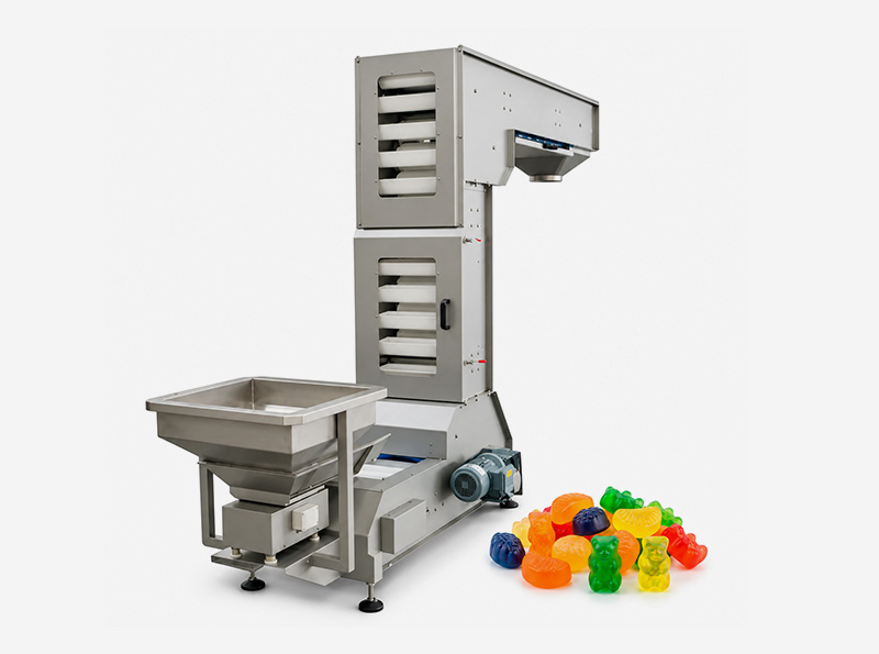
Feeder for gummies
If capsules, tablets, or gummies use an elevator for feeding, include its lift path and discharge position in the height review. Confirm the selected cap-feeding and sleeve-labeling configurations as well. The counter’s height alone does not represent the whole line.
Beyond the highest point of a stationary machine, check whether loading, opening covers, or maintenance needs additional overhead space. Use the actual equipment instructions and working methods rather than applying one ceiling-height requirement to every model.
When sending building information, mark the lowest beam undersides, pipework, and other fixed overhead obstacles. Put those restrictions on the drawing before locating taller equipment, so the floor plan and height can be checked together.
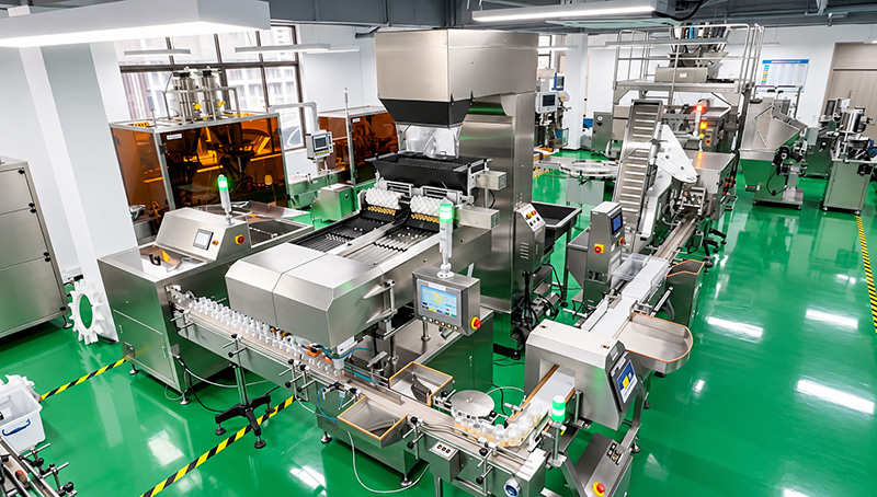
Taller equipment and local clear height
5.Line layouts: straight, L-shape, or U-shape
Straight, L-shaped, and U-shaped layouts are all possible starting points. The choice depends on room shape, doors, columns, material routes, and connections between stations. Turns and return legs may help use the available space, but they also create access requirements. Compare how the line will work, as well as its outline.
Straight: use available continuous length
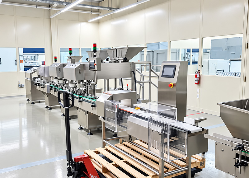
Where the room has enough continuous length, arranging successive operations in one direction is usually straightforward. Check access at both ends, operation on both sides, and how people move around the line. Include those routes while allocating the length.
L-shape: work with a corner or two sections of space
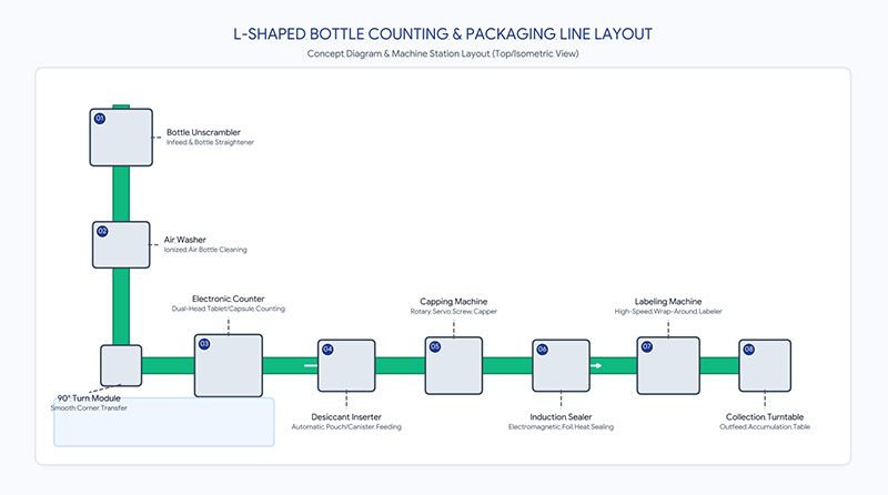
Consider an L-shape when using a room corner, working around a fixed obstruction, or running the front and back sections in different directions. Check the conveyor turn, space beside columns, and whether the turned section blocks a door or service side.
U-shape: bring the infeed and discharge closer
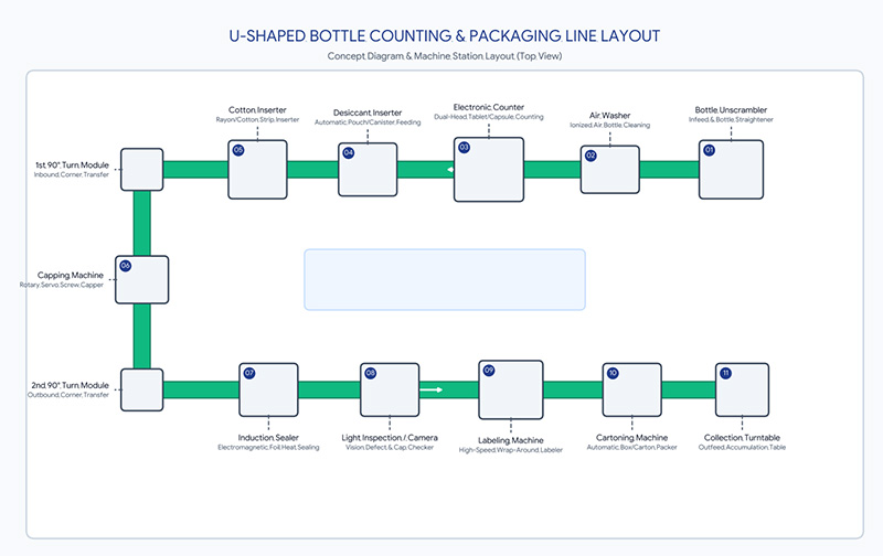
In a suitable room, a U-shape can bring the ends closer and help operators oversee different positions. Check access to inside stations, material replenishment, and service space on both sides. It does not automatically use the least space or establish a fixed reduction in staffing.
| Layout | Conditions worth assessing | Key checks |
|---|---|---|
| Straight | Continuous room length and a process suited to one-direction flow | Access at both ends, side aisles, and maintenance |
| L-shape | A room corner or fixed obstruction to work around | Conveyor turn, space beside columns, and door locations |
| U-shape | A need for nearby ends and a room that allows a return leg | Inside access, replenishment, and service space on both sides |
Plan buffering around the actual bottle flow
Some faster lines use additional conveyor or accumulation sections to accommodate short-term rate differences between stations. Include their footprint and check bottle format, flow, and stop/start coordination. Allow for them during layout planning rather than after all available space has been allocated.
A buffer is not standard on every line, and it does not necessarily belong at a turn. Confirm whether it is needed, where it should sit, and how it works with neighboring equipment for the actual configuration and operating requirements.
Three shapes: keep the sequence and check access
Straight
Check continuous length, access at both ends, and side maintenance.
L-shape
Check the turn, columns, and doors beyond the corner.
U-shape
Check inside access, replenishment, and service space on both sides.
Each shape is a starting point. Confirm conveyor connections and buffering for actual bottles, equipment, and rates. A U-shape does not automatically save space or staffing.
The sketches use different scales and cannot compare floor areas. Numbers show the same process sequence. Redraw actual equipment, turns, buffers, and working areas for the project.
6.Plan primary and secondary packaging areas separately
Plan primary and secondary packaging areas separately before finalizing the layout. Whether they need separate rooms, where the boundary belongs, and how products pass between them depends on the product, process, and site-management requirements. Placing every machine in one open room does not complete those planning decisions.
Counting into bottles and closing the containers, for example, can be planned as a different work area from subsequent cartoning and case packing. Where labeling belongs also depends on the actual process; the machine name alone does not determine its area.
If separate rooms are required, walls, doorways, and cross-boundary conveyor positions affect equipment placement. Show how operators and packaging reach their respective stations and how closed bottles transfer between the areas on the same drawing.
For supplement bottling, first specify the clean, controlled production conditions and packaging methods the product needs. Then determine the area arrangement. We do not assume the same room classification for every project; the point here is to include the space needed for separation and process connections.
Plan the boundary and product transfer together
The diagram shows work areas and transfer relationships only. Confirm separate rooms, doorways, and cross-boundary conveyor interfaces for the project.
7.There's no magic formula: we lay it out for you
There is no universal formula for a bottling line’s floor space. The requirement changes with equipment, layout shape, maintenance needs, and building constraints. We provide standard machine dimension drawings and a free initial layout and space check based on your actual room, giving you a drawing to review rather than a rough guess.
Send complete room and production information
| Information to provide | Details |
|---|---|
| Room dimensions | Usable length, width, and height; lowest beams and pipework at relevant positions |
| Fixed features | Doors, windows, columns, existing partitions, and equipment that must stay; photos or a sketch |
| Products and packaging | Product types and dimensions, count per bottle, bottle and cap specifications |
| Production requirements | Target output, batch schedule, and any desiccant, sleeve-labeling, or other stations |
| Working methods | Operator and replenishment positions, incoming and outgoing routes, staging, and packaging-area arrangements |
| Existing equipment connections | Equipment to retain, intended positions, and known interfaces or space restrictions |
Check equipment and working space on one drawing
We can provide standard dimension drawings for the corresponding machine configuration and prepare a layout using your site information. Review machine footprints, service sides, operator and material routes, and taller equipment together to identify suitable positions and areas needing adjustment.
For a tight room, compare straight, L-shaped, and U-shaped options or assess different equipment combinations around the processes you need. Our anthor article “Complete Line or Core Machines Only? How to Decide What to Buy” discusses a complete line versus retaining existing equipment; the layout turns that choice into actual positions.
Reconfirm dimensions and site conditions after selecting the configuration
An initial layout helps establish the direction of the plan. Final placement still needs to reflect the selected models, accessories, site checks, and confirmed configuration. Recheck the space assessment if the equipment or building conditions change.
Have us lay out the actual room before committing to a production area or arranging alterations. You can then see the space needed, check the routes, and identify issues to resolve before the equipment arrives.
Frequently asked questions
It depends on equipment, layout shape, maintenance access, aisles, buffering, and area separation. No single floor-space multiplier applies to every project. Send your production requirements and room dimensions, and our factory can prepare a free initial layout and space check.
Confirm this from the machine’s service side, door and cover openings, parts removal, and working-space requirements. A door opening alone is not enough, and one wall clearance should not be applied to every machine. Check neighboring equipment and columns too.
Product elevators, cap elevators, and sleeve labelers may be taller than other stations. Check clear height at their actual locations for the selected configuration, including loading, cover opening, and maintenance. Provide beam and pipework positions as well.
We can assess that using actual site information. Send the room dimensions, doors, columns, existing equipment, and production requirements. We will prepare a free initial layout to check equipment placement, access, and maintenance. Total floor area alone cannot establish that the line fits.
Use room shape, door and column positions, material routes, and equipment connections. For a straight line, check continuous length; for an L, the turn; for a U, inside access and replenishment. All three need appropriate operating and service space.
Plan the areas separately, then confirm whether separate rooms are needed and how to divide and connect them for your product, process, and site-management requirements. Check boundaries, doorways, people and packaging routes, and product transfer as part of the layout.
Yes. Our machines are certified and use certified electrical components. Because the exact scope depends on the model and electrical configuration you select, our factory confirms it in writing before production.
LET’S PLAN YOUR FLOOR SPACE
Send AIPAK your available room’s length, width, and height, door, window, and column locations, plus your product, bottle, cap, and output requirements. Our factory provides a free initial layout and space check to assess equipment placement, maintenance, movement, and loading conditions for the proposed configuration.
Prefer to talk it through? +1 (213) 526-8644
Allow for maintenance, people, materials, and loading height. There is no universal area multiplier; we can prepare a free initial layout for the actual room.